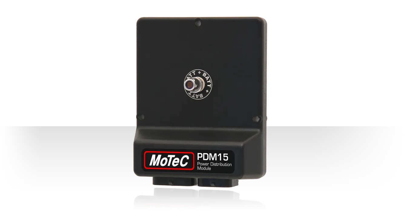
PDM15

VISIÓN GENERAL
MoTeC’s 15 output Power Distribution Module is designed to provide electronically switched power to the various electrical systems in the vehicle such as motors, lights, solenoids, and electronic devices such as ECUs and data acquisition systems.
The module replaces conventional relays, fuses and circuit breakers to simplify wiring and switch requirements, while increasing reliability.
CARATERISTICAS
- Each output is over-current, short circuit and thermal overload protected
- Outputs programmable in 1 A steps and controllable via a combination of switch inputs, CAN messages and logic functions
- Performs up to 200 logic operations and functions that can be used to selectively turn off systems
- Provides full diagnostic information via CAN
ACCESORIOS
- Inputs
- 16 x switch inputs: range 0 to 51 V, resolution 0.2 V
- Outputs
- 8 x 20 A outputs: 20 A continuous, 115 A transient (typical)
- 7 x 8 A outputs: 8 A continuous, 60 A transient (typical)
- Communications
- 1 x CAN
- Operating Voltage
- 30 V max
- Ingress Protection (IP) Rating
- Conformal coating on PCB
- Physical
- 1 x 34 and 1 x 26 pin waterproof connectors, 1 x M6 stud
- Case size 107.5 x 127.5 x 38.7 mm
- Weight 260 grams
COMPATIBILIDAD
MoTeC ECU Models
- M1 Series (package dependent)
- Discontinued: M84, M400, M600, M800, M880
MoTeC Dash/Logger Models
- C125, C127, C1212, C185, C187, C1812, CDL3, L120, L180
- Discontinued: SDL, SDL3, ADL, ADL2, ADL3, ACL
SOFTWARE
Latest software can be found in downloads below
PDM Manager software is used for:
- Configuring all inputs, outputs, CAN messages and conditions
- Monitoring all channel values
- Output testing
- Firmware updating
CABLEADO
CAN Wiring
The PDM is wired onto the CAN bus. Please ensure wiring is according to CAN requirements and the CAN bus has at least one 100R terminating resistor. More information can be found in the user manual located in the downloads below
To communicate to the PC, a CAN connector must be wired into the CAN bus. To connect the PDM directly to the CAN connector, wire according to the following table.
| PDM Pin | PDM Name | CAN Connector Pin | CAN Connector Wire |
|---|---|---|---|
| B25 | CAN Lo | 4 | Green |
| B26 | CAN Hi | 5 | White |
| A28 | 0 V | 1 | Black |
Example Wiring
Wire Gauges
Suitable wire gauges are 24# to 20# for the 8 A outputs and 20# to 16# for the 20 A outputs. The wire gauge must be chosen to suit the current consumed by the connected device and to ensure that the voltage drop is acceptable. In a long run it may be necessary to use a heavier gauge wire to minimise voltage drop. The wire gauge must also be compatible with the connector pin; using a smaller than recommended wire gauge may result in a poor crimp.
DIMENSIONES Y MONTAJE
Measurements in mm.
The product provides through holes for mounting. See drawing for details.
Recommended mounting torque value is 5 Nm. The torque value must not exceed 5.5 Nm.
A mounting drawing or a surface CAD model is available upon request from MoTeC
PINOUT
Connector A
34 pin waterproof connector, mating connector #65044
| Pin | Name | Function |
|---|---|---|
| A1 | OUT1 | 20 A Output 1 (with A10) |
| A2 | OUT9 | 8 A Output 9 |
| A3 | OUT2 | 20 A Output 2 (with A12) |
| A4 | OUT10 | 8 A Output 10 |
| A5 | OUT3 | 20 A Output 3 (with A14) |
| A6 | OUT11 | 8 A Output 11 |
| A7 | OUT4 | 20 A Output 4 (with A16) |
| A8 | OUT12 | 8 A Output 12 |
| A9 | OUT5 | 20 A Output 5 (with A17) |
| A10 | OUT1 | 20 A Output 1 (with A1) |
| A11 | OUT13 | 8 A Output 13 |
| A12 | OUT2 | 20 A Output 2 (with A3) |
| A13 | OUT14 | 8 A Output 14 |
| A14 | OUT3 | 20 A Output 3 (with A5) |
| A15 | OUT15 | 8 A Output 15 |
| A16 | OUT4 | 20 A Output 4 (with A7) |
| A17 | OUT5 | 20 A Output 5 (with A9) |
| A18 | Not used | |
| A19 | DIG2 | Digital/Switch Input 2 |
| A20 | Not used | |
| A21 | DIG4 | Digital/Switch Input 4 |
| A22 | Not used | |
| A23 | DIG7 | Digital/Switch Input 7 |
| A24 | Not used | |
| A25 | Not used | |
| A26 | VBATT- | Battery Negative |
| A27 | DIG1 | Digital/Switch Input 1 |
| A28 | GND | 0 V |
| A29 | DIG3 | Digital/Switch Input 3 |
| A30 | DIG5 | Digital/Switch Input 5 |
| A31 | DIG6 | Digital/Switch Input 6 |
| A32 | DIG8 | Digital/Switch Input 8 |
| A33 | DIG9 | Digital/Switch Input 9 |
| A34 | DIG10 | Digital/Switch Input 10 |
Connector B
26 pin waterproof connector, mating connector #65045
| Pin | Name | Function |
|---|---|---|
| B1 | Not used | |
| B2 | Not used | |
| B3 | OUT6 | 20 A Output 6 (with B9) |
| B4 | Not used | |
| B5 | OUT7 | 20 A Output 7 (with B11) |
| B6 | Not used | |
| B7 | OUT8 | 20 A Output 8 (with B13) |
| B8 | Not used | |
| B9 | OUT6 | 20 A Output 6 (with B3) |
| B10 | Not used | |
| B11 | OUT7 | 20 A Output 7 (with B5) |
| B12 | Not used | |
| B13 | OUT8 | 20 A Output 8 (with B7) |
| B14 | Not used | |
| B15 | DIG13 | Digital/Switch Input 13 |
| B16 | Not used | |
| B17 | DIG15 | Digital/Switch Input 15 |
| B18 | VBATT- | Battery Negative |
| B19 | Not used | |
| B20 | DIG11 | Digital/Switch Input 11 |
| B21 | DIG12 | Digital/Switch Input 12 |
| B22 | GND | 0 V |
| B23 | DIG14 | Digital/Switch Input 14 |
| B24 | DIG16 | Digital/Switch Input 16 |
| B25 | CAN Lo | CAN Low |
| B26 | CAN Hi | CAN High |
Connector C
M6 stud, mating: eyelet and M6 nut
| Pin | Name | Function |
|---|---|---|
| C1 | VBATT+ | Battery Positive |
INFORMACION DEL PRODUCTO
Compliances
This product is designed for use in a vehicle. As such, this product complies with the following standard: Directive 2014/30/EU: Electromagnetic Compatibility; by application of UNECE Regulation No.10 (R10) Rev 6 20/11/2019
Installation
IP Rating (dust or water ingress)
This product should be installed in a protected location where only occasional water splashing occurs and where the exposure to dust does not exceed conditions typical for vehicle installations.
Operating Temperature Range
This product is designed for an internal operating temperature range of -40 °C to 85 °C.
It should be installed in a location with sufficient air circulation and be shielded against thermal emissions from surrounding components.
Vibration Statement
This product is designed to withstand vibrations typical for normal vehicle installations.
It should not be exposed to severe and lasting vibrations. For example, the product should not be installed in solid connection to vibrating components like engines or undamped vehicle structures.
Safety
- For safe operation, use only undamaged.
- Minimal force should be exerted to plug in connectors.
- These devices may output voltages which may constitute a risk to human safety. Appropriate precautions must be taken:
- At no time operate the device with faulty, bare or exposed wiring.
- Adhere to the normal supply voltage limits as listed in the Basic Specifications section
- Adhere to wire gauges as listed in Wiring and Connecting.
Repair
Do not attempt to open and/or repair the device.
Disposal

This product should be disposed of in accordance with relevant national regulations for disposal of electronic waste. It does not contain hazardous materials which might be subject to specific materials regulations.