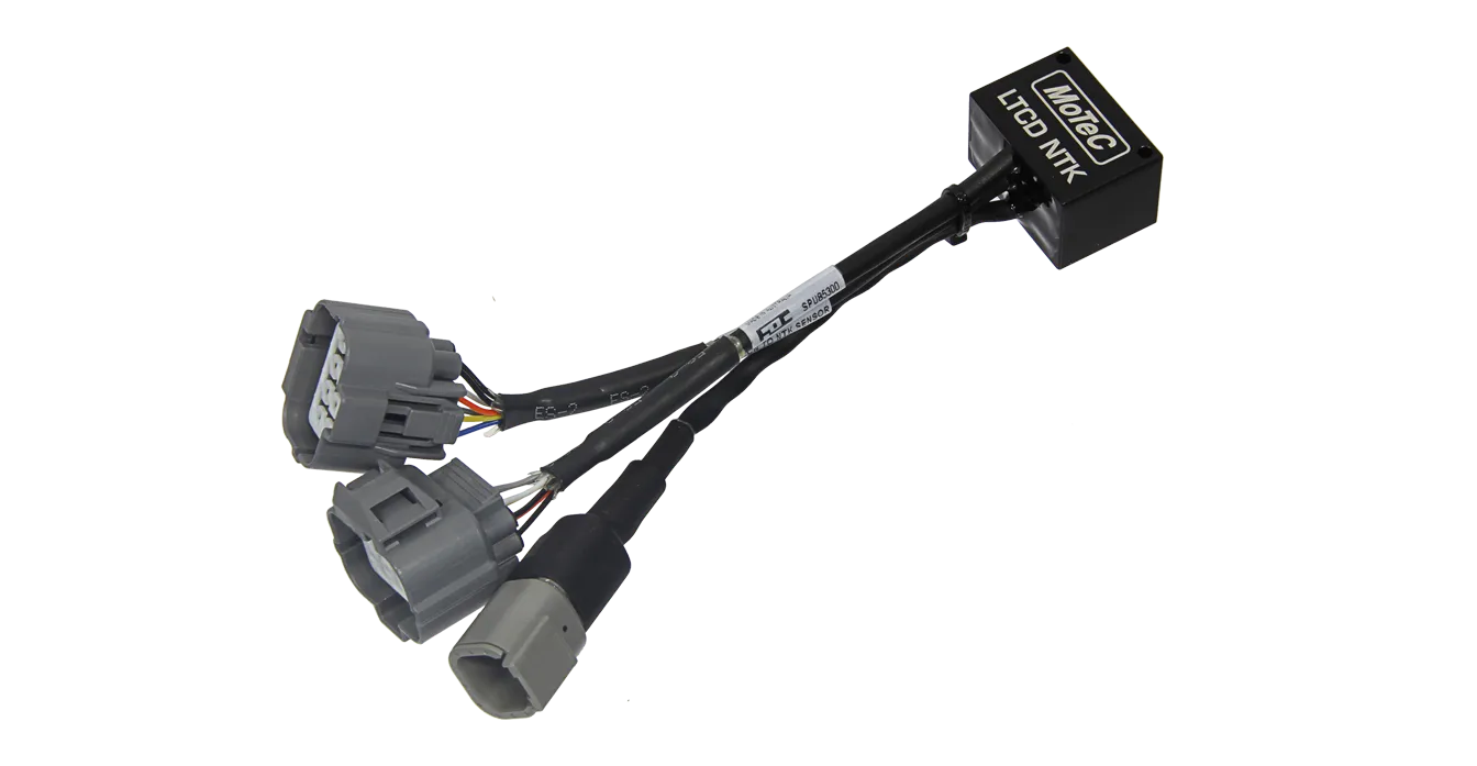
LTCD NTK

VISION GENERAL
MoTeC’s LTCD NTK (Lambda To CAN) is the dual sensor version of the LTC NTK. It monitors, controls and diagnoses two NTK Lambda sensors, transmitting Lambda readings on a CAN bus. When using Dual LTCs or a mix of singular and Dual LTCs, up to 32 Lambda sensors can be configured on a single CAN bus for simultaneous monitoring by an ECU or logging device.
FUNCIONES
- Provides accurate Lambda measurement, even when exhaust gas temperature is changing rapidly (heating or cooling).
- Calibrated by the user for a particular sensor using the initial sensor factory calibration, the free air calibration or the referenced gas calibration.
- Pre-configured to suit a single unit installation. If necessary, the configuration can be adjusted; see the Configuration section for more details.
- Units marked with a 2 or higher under the barcode are able to transmit extended Lambda values (Rich Lambda).
ESPECIFICACIONES
Inputs/Outputs
- 2 x NTK Lambda sensor (MoTeC #57007)
- Power supply voltage for each sensor 11 V – 16 V
- Power supply current for each sensor 110 mA typical plus the sensor heater current. Heater current is typically 0.5 A – 1 A and up to 2 A on startup.
Communications
- 1 x CAN – using LTC Manager, configurable to: 125 Kbps, 250 Kbps, 500 Kbps or 1 Mbps
Physical
- Dimensions: 38 x 26 x 23.5 mm, excluding wiring looms and connectors
- Weight: 100 g
- 1 x 4 pin male DTM connector (power/CAN)
- 2 x mating connectors for NTK Lambda sensor
- Maximum ambient temperature: 100 °C
SOFTWARE
For multiple installations, LTC Manager software allows all units to be simultaneously managed and diagnosed.
The software is used to:
- Configure and calibrate all units on the CAN bus
- Display readings and diagnostics
- Configure CAN transmission addresses
- Control free air sensor calibration
- Update unit firmware
CONFIGURACION
MoTeC LTCDs come pre-configured to suit a single LTCD unit installation. By default, the initial factory sensor calibration is used and the following CAN addresses:
Sensor 1 – 460
Sensor 2 – 461
It is only necessary to use LTC Manager if installing multiple LTC units, or if changes to the default settings are required.
CONECTORES PINOUTS
Connector A (and B for Dual version)
NTK sensor connector
Mating connector: supplied on sensor
| Pin | Wire Colour | Description |
|---|---|---|
| 1 | Blue | Heater + |
| 2 | Yellow | Heater – |
| 3 | Orange | Rc |
| 4 | Black | Sensor 0 V |
| 5 | Not connected | |
| 6 | Grey | Vs |
| 7 | White | Ip |
| 8 | Black | Sensor 0 V |
Power / CAN Connector
DTM 4pin (M) (#68055)
Mating connector: DTM 4pin (F) #68054
| Pin | Wire Colour | Description |
|---|---|---|
| 1 | Black | Battery – |
| 2 | Green | CAN Lo |
| 3 | White | CAN Hi |
| 4 | Red | Battery + |
CABLEADO
To power the LTC, connect to either the ignition switch for fast sensor startup or the fuel pump relay to prevent accidental battery drainage.
Wiring example
For information on wiring a CAN bus with several LTCs and any number of other CAN devices (as per the example), refer to the relevant device manual.