5 BUTTON ROTARY CONTROLLER
VISIÓN GENERAL
MoTeC’s 5 Button Rotary Controller simplifies and centralises control within the cockpit, reducing the number of switches and dials required to make adjustments on the fly. It integrates with MoTeC Display Loggers, providing configurable functionality with a standard system and intuitive operation with MoTeC’s Colour Display Menu System when Display Creator is installed.
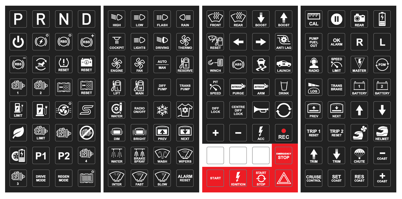
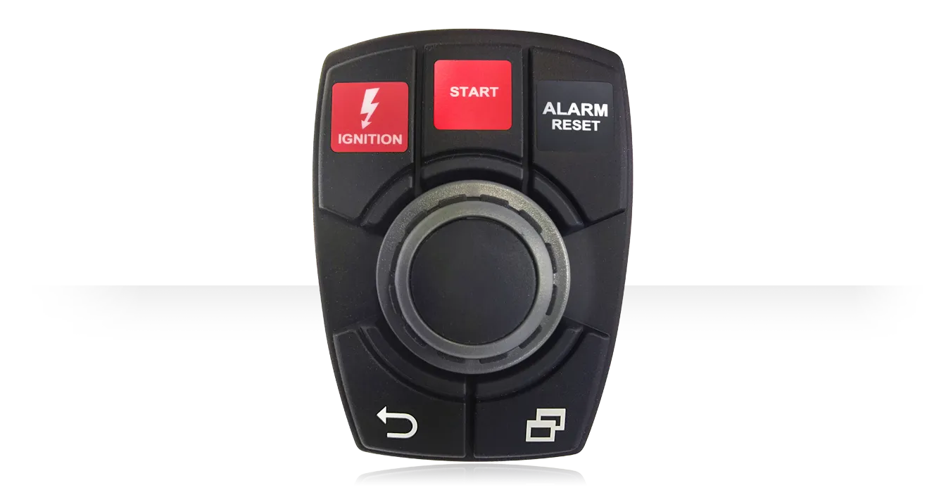
The controller features a Menu button, a Back button and three user-definable buttons that can be labelled with the supplied stickers for a professional finish.
The rotary dial itself is large and ergonomically designed with distinct increments during rotation. It is easy to grip and turn with precision, even while wearing gloves, enabling the driver or co-driver to operate the controller primarily by feel.
CARATERISTICAS
- Small, lightweight and ergonomically designed
- Rugged – vibration and impact resistant for use in extreme environments
- Dust and water resistant – sealed to IP67
- 5 x Backlit buttons:
- 1 x Menu
- 1 x Back
- 3 x User-defined (blank when supplied)
- Large selection of semi-transparent adhesive labels included
- Compatible with MoTeC’s Colour Display Menu System:
- Turn the dial to scroll through menu structures
- Press the dial to make a selection
- Supports multiple key press combinations
- Simplified wiring, only 4 wires required for multiple buttons
- Short circuit and reverse polarity protection
PART NUMBERS
- 41402 – 5 Button Rotary Controller (includes labels x 4 sheets)
- 63044 – Replacement Labels x 4 Sheets
ESPECIFICACIONES
Configuration
The device comes preconfigured for use with MoTeC Colour Display Loggers.
Communications
- Single CAN bus
Capacity on CAN bus
- Up to 2 Rotary Controllers
Advise your dealer if multiple Rotary Controllers are required on the same CAN bus. Use of multiple Controllers will require the units to be pre-configured before supply.
Power
- Operating voltage: 8 to 32 V DC
- Operating current: 0.2 A maximum
- Reverse battery protection
- Short circuit protection
Ambient operating temperature
- -40 °C to 85 °C
Physical
- 1 x 4 pin Deutsch DT connector
- Size (without connector): 110.65 x 79.36 x 51.26 mm
- Weight: 160 g
PINOUT
Mating Connector: MoTeC #68064
| Pin | Function | Pin | Function |
|---|---|---|---|
| 1 | Power | 3 | CAN-Hi |
| 2 | Ground | 4 | CAN-Lo |
DASH MANAGER SETUP
There are three communications templates required to use the 5 Button Rotary Controller with a MoTeC Display Logger:
- Rotary Controller – Button Rx Node ID 0x0E
- Rotary Controller – BL Tx Node ID 0x0E
- Rotary Controller – NMT Tx Node ID 0x0
These templates are supplied with Dash Manager version 6.10 onwards for MoTeC Colour Display Loggers. Templates for monochrome MoTeC Dash Loggers can be supplied on request by contacting MoTeC.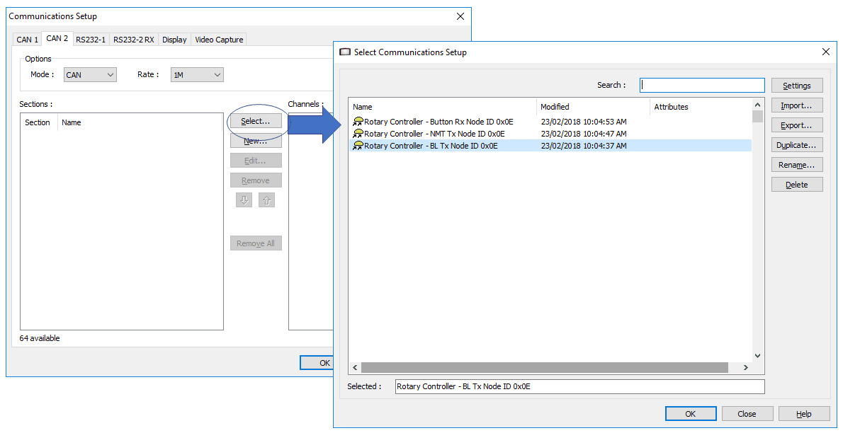
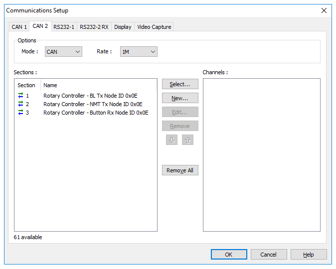
NOTE: The two transmit templates require channels to be set up in the Dash Manager configuration to work correctly.
These are the steps: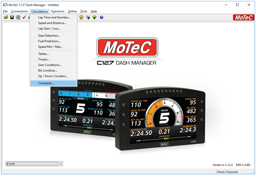
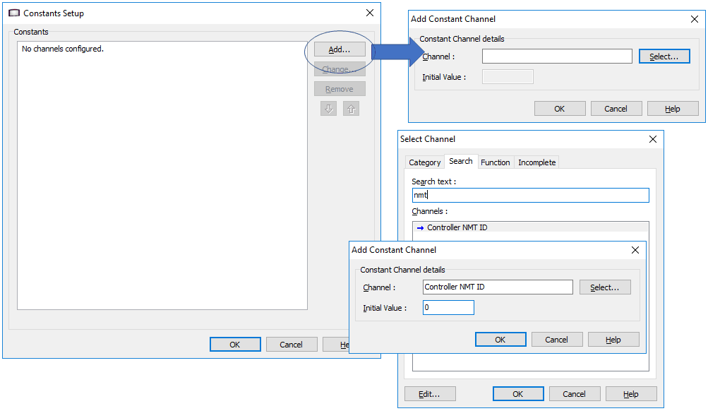
NOTE: The ‘Controller NMT ID’ channel must be set to zero for the Controller to operate correctly.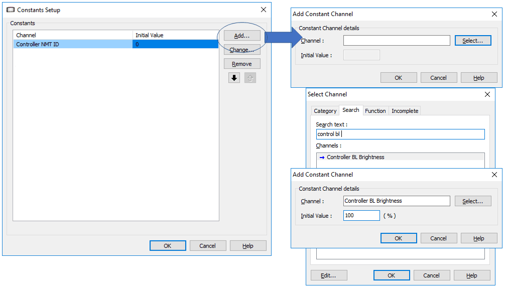
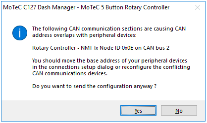
NOTE: The ‘Controller BL Brightness’ channel can be used to set the backlight brightness of the Controller from 0-100%. If different brightness values are required, this channel can be configured as part of another function, instead of as a constant.IMPORTANT: If you have a MoTeC Colour Display Logger running firmware older than V6.10, or any MoTeC monochrome Display Logger, you will receive the following warning message every time you send a configuration to the Display. You can simply click ‘Yes’ to continue sending the configuration; it will have no detrimental effect on the operation of the device.
KEYPAD AND PDM SETUP
The Rotary Controller can be used on the same CAN bus as a MoTeC Keypad and PDM, however, due to the functionality of the CANOpen protocol, the setup requirements differ from using a single device on the bus.IMPORTANT: The PDM only wakes up the Rotary Controller to avoid clashing messages with the Display Logger. The PDM cannot read button presses from the Rotary Controller; only the Display Logger can read the channels.
Display Setup
Add both the Rotary Controller – Button Rx Node ID 0x0E and Rotary Controller – BL Tx Node ID 0x0E templates to the Display Logger configuration as per the previous steps, but do not add the Rotary Controller – NMT Tx Node ID 0x0E template.
The ‘Controller NMT ID’ channel does not need to be configured in the Constants setup.
PDM Setup
In PDM Manager, configure one of the spare Keypads with the ‘CANOpen Node ID’ as 0E. The other parameters are not required and can be left as the defaults. See following image:
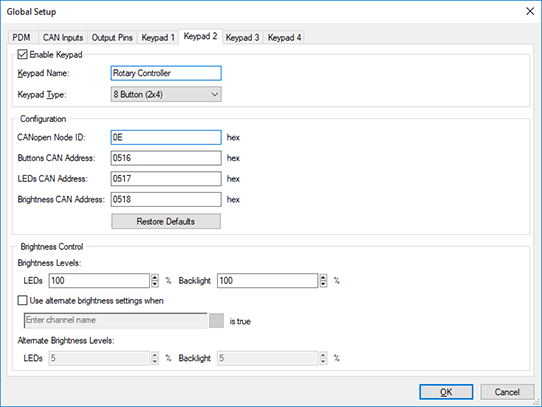
NOTE: Any spare Keypad tab can be used for setup.
