L120 (USB)

VISIÓN GENERAL
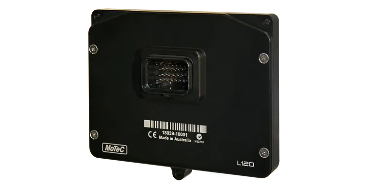
The L120 Enclosed Logger (USB) is a powerful control device and fully programmable data logger, all in one compact unit.
It comes standard with 120MB internal memory plus USB logging for additional data capacity, convenience and flexibility.
The L120 acquires data from other devices, such as an ECU, for logging and telemetry. It can be used in a wide range of applications, either as a standalone unit or integrated with other electronic devices such as displays and PDM’s.
Note: An L120 Enclosed Logger without USB Logging is also available. (Part #18039)
CARACTERISTICAS
- Suitable for bikes, cars, marine and industrial applications
- USB Logging
- 120MB internal logging memory
- GPS Lap Timing
- Supports Wideband Lambda from MoTeC PLMs or LTCs
- Easily integrates with MoTeC CAN based products such as ECUs and expanders
- Full I/O expansion available with use of E888, E816 expanders
ACCESORIOS
- 62204 – L120 LOOM
- 61259 – L120 INPUT LOOM
- 61279 – CABLE USB LOGGING 1.5M (PANEL MOUNT)
- 61403 – CABLE, AUTOSPORT USB LOGGING 1.5M (PANEL MOUNT)
- 61280 – 32 GB USB DATA PLUG
- 61292 – 32 GB USB3 FLASH DRIVE
MEJORAS OPCIONALES
- 29624 – L120 T2 TELEMETRY
- 29621 – L120 PRO ANALYSIS
- 29601 – L120 I/O
ESPECIFICACIONES
Communications
- 2 x configurable CAN buses, with individually programmable CAN bus speeds.
- One can be used as RS232 Receive
- 2 x dedicated RS232 ports
- One with Transmit and Receive
- One with Receive only
Inputs
(* available via I/O upgrade)
- 2 x digital inputs
- 3 x speed inputs
- 6* x analogue voltage inputs:
- 4* x 0 to 5.46 V, 1.33 mV resolution
- 2* x 0 to 15.0 V, 3.66 mV resolution
- 2* x analogue temperature inputs, 0 to 15 V, 3.66 mV resolution
Outputs
(* available via I/O upgrade)
- 4* x low side outputs PWM or switched operation
- 0.5 A maximum, current limited and thermal overload protected
Logging
(available via upgrades)
- 120 MB internal logging memory
- USB logging to a removable storage device
- Logging rates up to 500 samples per second
- Fast Ethernet download
Internal Sensors
- 3-axis accelerometer, detection range: +/- 5G
- Sensor supply voltage
- Battery voltage
Power supply
- Operating voltage: 6 to 32 V DC
- Operating current: 0.5 A typical at 14 V (excl. sensor currents)
- Reverse battery protection
- Battery transient protection
Sensor supply currents
- 5 V sensor supply: 0.25 A maximum
- 8 V sensor supply: 0.25 A maximum
Operating temperature
- Internal: -20 °C to 70 °C
- Typical ambient temperature range in free air: -20 °C to 55 °C
Physical
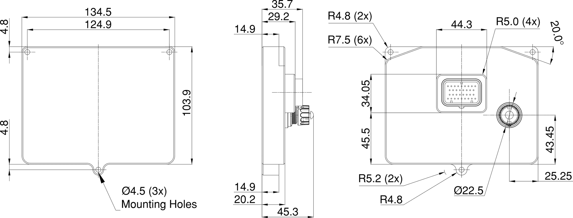
- Unit size: 134.5 x 103.9 x 20.2 mm excluding connector
- Weight 310 g
- 1 x 34 pin waterproof connector
- 1 x mini USB port (type B)
- The device is rated to IP67
COMPATIBILIDAD
- MoTeC ECUs: All models (some earlier models may require an additional adaptor in conjunction with the RS232 adaptor)
- MoTeC Displays/Loggers: All
- MoTeC Expanders: E816 and, E888 expanders.
- MoTeC Accessories: SLM, PLM, LTC, BR2, PDM, GPS, ADR2, V2 etc.
- Many non-MoTeC devices
SOFTWARE
- Microsoft Windows based software
- Used for setup and management of the data logging system, providing:
- Configuration of the inputs, ouputs, data logging and calculations.
- Offline generation of a configuration file that can then be sent to the device.
- Channel monitoring
- Firmware updating and extensive help screens
- i2 Data Analysis software provides the tools for comprehensive data analysis. Standard or Pro* version available
- T2 Telemetry* software
CABLEADO DE LA ECU
When using an M4, M48 or M8 ECU, the L120 should be connected via RS232. For some ECUs, a PCI cable may also be required.
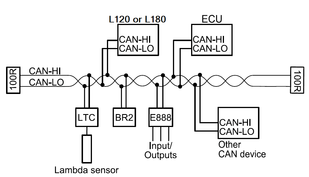
The Display Logger should be connected via the CAN bus when using an M1 or ‘hundred series’ ECU(M400/M600/M800/M880) or M84, and any number of other CAN devices. Example:

Detailed wiring information is available in the help topics of the C125 Dash Manager software
DIMENSIONES Y MONTAJE
Measurements in mm.

PINOUT
Mating Connector: Part number 65044
| Pin | Name | Standard Function | Optional Function (with I/O upgrade) |
|---|---|---|---|
| 1 | E-TX– | Ethernet Transmit – | |
| 2 | E-TX+ | Ethernet Transmit + | |
| 3 | AV1 | Analogue Voltage Input 1 | |
| 4 | AV2 | Analogue Voltage Input 2 | |
| 5 | AV3 | Analogue Voltage Input 3 | |
| 6 | AV4 | Analogue Voltage Input 4 | |
| 7 | 8V | Sensor 8 V | |
| 8 | 5V | Sensor 5 V | |
| 9 | 0V | Sensor 0 V | |
| 10 | E-RX– | Ethernet Receive – | |
| 11 | E-RX+ | Ethernet Receive + | |
| 12 | AV5 | Analogue Voltage Input 5 | |
| 13 | AV6 | Analogue Voltage Input 6 | |
| 14 | DIG1 | Digital Input 1 | |
| 15 | DIG2 | Digital Input 2 | |
| 16 | AT1 | Analogue Temp Input 1 | |
| 17 | AT2 | Analogue Temp Input 2 | |
| 18 | CAN1L | CAN1 Lo | |
| 19 | CAN1H | CAN1 Hi | |
| 20 | RS232-1 TX | RS232-1 Transmit Output | |
| 21 | SPD1 | Speed Input 1 | |
| 22 | SPD2 | Speed Input 2 | |
| 23 | SPD3 | Speed Input 3 | |
| 24 | Not used | Not used | |
| 25 | RS232-2 RX | RS232-2 Receive Input | |
| 26 | CAN2L | CAN2 Lo / RS232 Ground Input | |
| 27 | CAN2H | CAN2 Hi / RS232 Receive Input | |
| 28 | RS232-1 RX | RS232-1 Receive Input | |
| 29 | AUX1 | Auxiliary Output 1 | |
| 30 | AUX2 | Auxiliary Output 2 | |
| 31 | AUX3 | Auxiliary Output 3 | |
| 32 | AUX4 | Auxiliary Output 4 | |
| 33 | BAT+ | Battery Positive | |
| 34 | BAT– | Battery Negative |
DESCARGAS