IGNITION SYSTEMS
VISION GENERAL
How to Choose
To decide which products to use for your ignition system consider the following factors:
Trigger System
The ignition timing is triggered by the engine position. A Ref signal indicating crank shaft position and a Sync signal indicating camshaft position (optional) provide this information to the ECU. Many different types of trigger sensors may be used. These signals can be derived from the OEM system or by using MoTeC’s trigger wheels and crank and cam sensors.
ECU
The ECU calculates the engine position from these Ref/Sync signals, and applies the appropriate ignition timing. The number of ignition output signals needed in a particular application depends on the engine (number of cylinders) and the ignition mode. If the number of ignition outputs available on the ECU is not sufficient, this can be increased by using a MoTeC IEX.
Inductive Ignition versus CDI Systems
In an inductive ignition system, the coil is charged at battery voltage for a period of time—known as ‘dwell time’—prior to firing. The dwell or charge time is controlled by the ECU and should match the coil being used in order to not over or under charge. Undercharging reduces available spark energy, while overcharging can cause overheating of the coil and/or ignition module. Inductive ignition systems produce a spark, at a lower voltage with a longer duration compared to capacitor discharge ignition systems.
A CDI, Capacitor Discharge Ignition system is charging constantly and sends a large voltage charge (380–450 V) to the coil. The spark produced is extremely short in duration and at a much higher voltage than an inductive setup. Note that inductive coils should not be used with a CDI system; CDI compatible coils are required.
There are three main engine running characteristics to consider:
- High cylinder pressures: Generally, higher cylinder pressures require more voltage to initiate a spark. Boosted or nitrous injected engines create tremendous cylinder pressures that increase resistance to lighting the ignition spark. CDI systems are most often used on these engines.
- High RPM: The time available to charge the coil in an inductive system reduces at higher RPM. If the time available is shorter than the time required for a full charge, coil power and, as a result, performance will be reduced. A CDI system might be required.
- Lean mixtures: The shorter spark duration in CDI systems might not be sufficient to ignite enough of the mixture to propagate the flame front through the cylinder. Inductive ignition will perform better in this setup.
Most vehicles, including high performance road and race applications use an inductive ignition system. Generally, if your engine can run correctly on an inductive setup, it is better to leave it that way and install a CDI system only when your engine, due to high RPM or cylinder pressure, requires that you do so.
Charging the Coils
The ignition signal is provided to the ignition module that controls the coil. Choose either inductive or capacitive discharge ignition modules with the correct number of channels.
Distributor
Depending on the ignition mode your application might need a distributor to deliver the spark to the relevant cylinder.
Ignition Coils
Depending on your system, choose either inductive or capacitive discharge ignition coils.
INDUCTIVE IGNITION MODELOS
124 – single channel ignition module
Part No: #41124
200 – dual channel ignition module
Part No: #41200
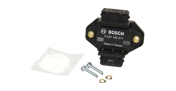
211 – four channel ignition module
Part No: #41211
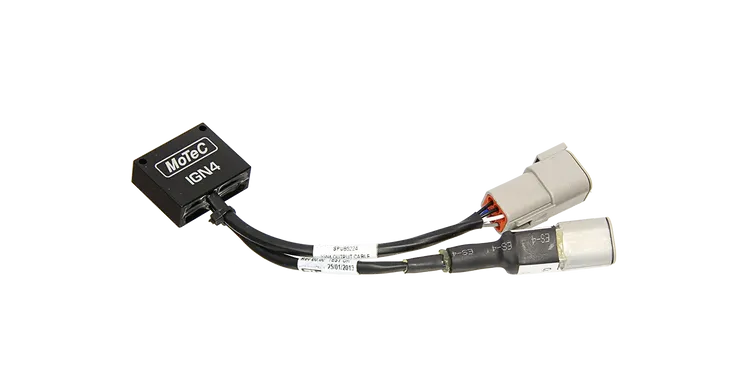
IGN4 Ignition Module
4 Channel
Part No: #41212
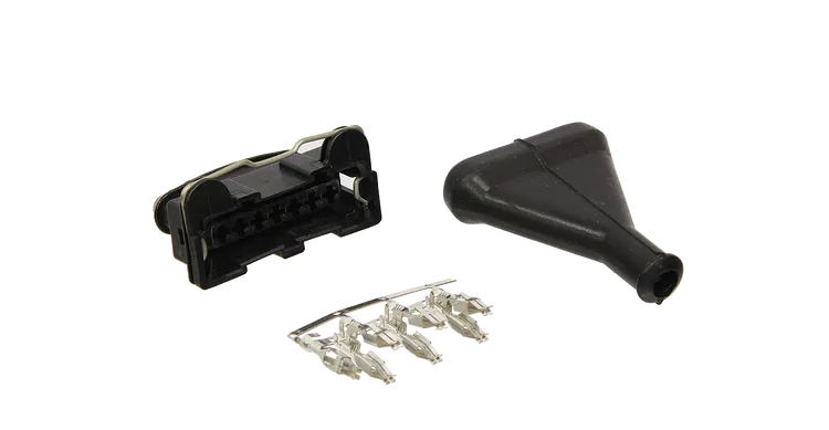
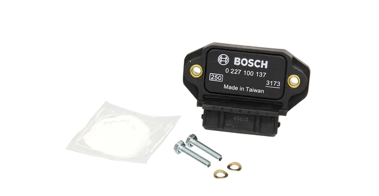
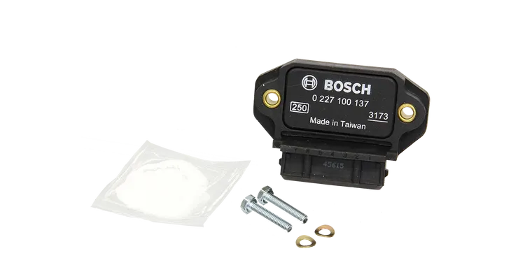
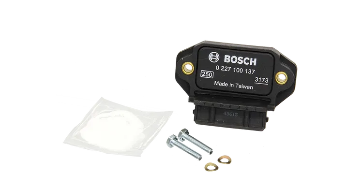
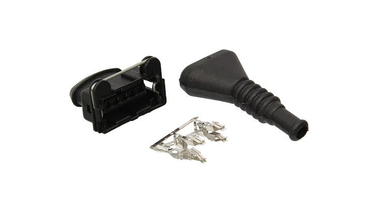
7 Pin Bosch Ignition Module
Connector Kit
Part No: #65010
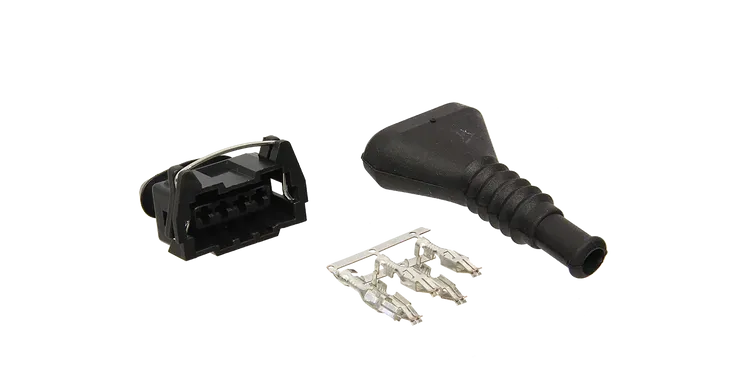
4 Pin Connector Kit
fits 209 / 211 Module
Part No: #65021
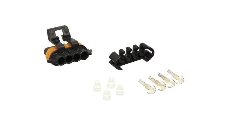
5 Pin Connector
fits 211 Module
Part No: #65023
4 Pin Connector
fits Denso Coil #42015
Part No: #67011
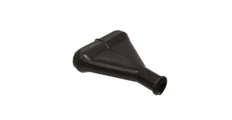
7 Pin Ignition Module Boot
Part No: #67008
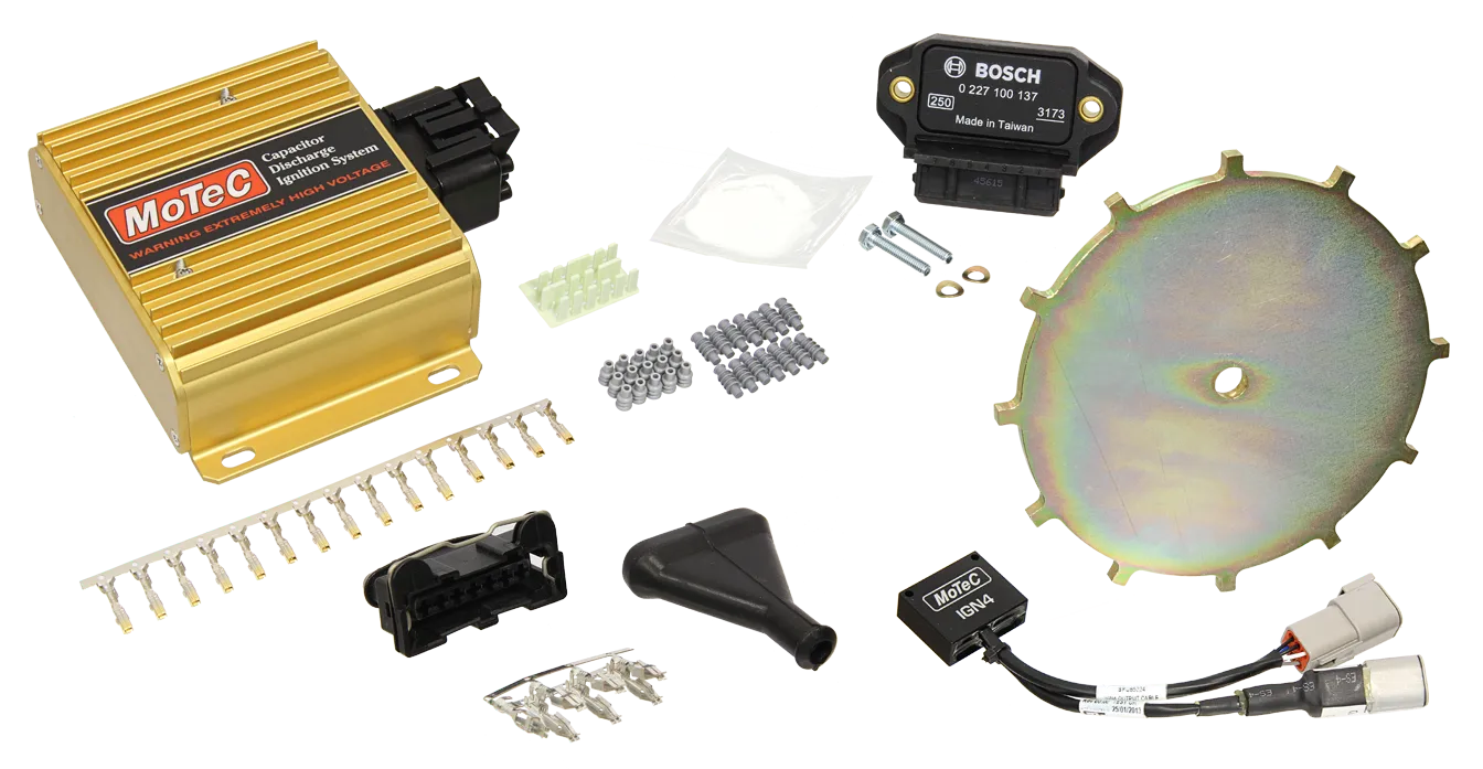
CDI MODULES
CDI-8
Designed to drive up to eight low-impedance CDI coils, the CDI-8 effectively combines an 8 channel ignition expander with an 8 channel CDI module in one compact unit. The circuitry can reliably deliver 450 volt primary voltage at 15 000 RPM (or at 30 000 RPM for 4 cylinders). The output stages deliver up to 200 A into the CDI coil primary.
CDI rotary, single channel, twin channel, four channel, Porsche replacement
These units are designed for single and dual coil CDI applications using conventional distributed spark, or for rotary applications. More than 100 millijoules of energy is available per spark. The hardware is produced to operate reliably in this kind of condition in a racing environment.
Important note:
Newer versions of the single, dual and four channel CDIs are not direct plug-in replacements for the earlier versions; some wiring changes are required. Refer to the relevant datasheets or contact us for more information. See superseded CDI modules below.
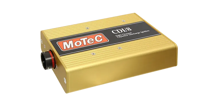
CDI-8 Eight Channel
(MX00 Series Compatible)
Part No: #14004
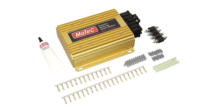
CDI 8
8 Channel
(M1 Series Compatible)
Part No: #41015
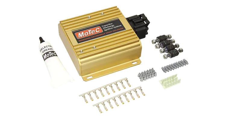
CDI Twin Channel
Part No: #41010
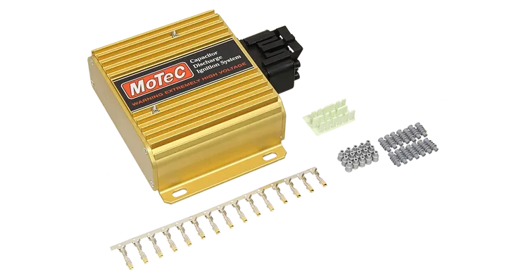
CDI – Ignition Module for Porsche
Part No: #41018
Superseded CDI units
| Product | Details |
| Part No: #41004 | CDI single channel |
| Part No:#41009 | CDI single channel |
| Part No:# 41013 | CDI single channel |
| Part No: #41005 | CDI dual channel |
| Part No:# 41003 | CDI four channel |
| Part No:# 41011 | CDI four channel |
| Part No:# 41012 | CDI Rotary four channel |
INDUCTIVE IGNITION COILS
Coils can be set up in different configurations—coil per cylinder, wasted spark or distributor. Choose an ignition coil compatible with the ignition mode in your application.
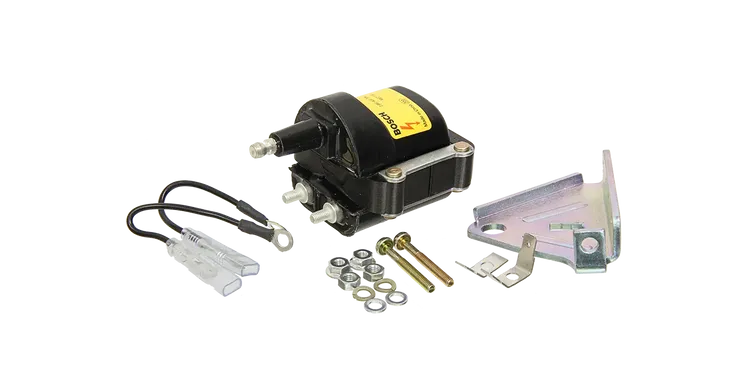
MEC718 Coil
Male end
Part No: #42001
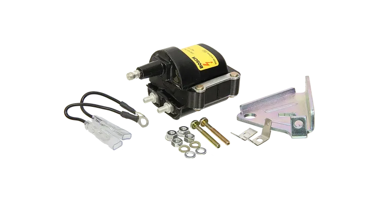
MEC717 Coil
Female end
Part No: #42014
CDI COILS
Coils can be set up in different configurations – coil per cylinder, wasted spark or distributor. Choose an ignition coil compatible with the ignition mode in your application.
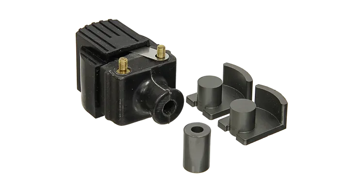
Mercury CDI coil
Part No: #42024
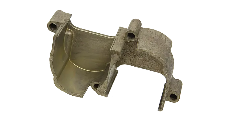
Cover for 2 CDI Coils
- Aluminium
Part No: #42025
